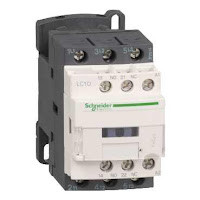
Contactors:
The contactors should comply with the latest IEC 60947-4-1 and the corresponding IS13947-4-1 standards. They shall have UL and CSA approval. The contactors should be rated for AC3 duty at 415V and 50Hz. The contacts should be fast closing and fast opening type.
The making and breaking capacity values of the contactors should be as follows (as per
IEC60947-4-1). However, higher making & breaking capacity helps in using the contactor in extreme conditions.
IEC60947-4-1). However, higher making & breaking capacity helps in using the contactor in extreme conditions.
For AC3 Duty
– Making Capacity equal to or more than 10 Ie
– Breaking Capacity equal to or more than 8 Ie
– Making Capacity equal to or more than 10 Ie
– Breaking Capacity equal to or more than 8 Ie
For AC4 Duty
– Making Capacity equal to or more than 12 Ie
– Breaking Capacity equal to or more than 10 Ie
– Making Capacity equal to or more than 12 Ie
– Breaking Capacity equal to or more than 10 Ie
The contactors should be capable of frequent switching and should operate without derating at 60 Deg.C for AC3 applications. They should be climate proof, as standard. The contactor should be operable without derating ± 30°, in relation to normal vertical mounting plane. The contactor should have protection against direct finger contact from front face to assure safety. The coil of the contactor should have class H insulation to support frequent switching.
It should be resistant to flame, shock and vibration to support the use of contactor in adverse condition. The contactor should operate without derating up to 3000 m.
The rated voltage of the contactor shall be equal or superior at 690 V, and rated insulation
voltage shall be 690 V up to 38 A & 1000 V above that. The rated impulse voltage of the
contactor should be 6 kV up to 38A & 8 kV above that.
voltage shall be 690 V up to 38 A & 1000 V above that. The rated impulse voltage of the
contactor should be 6 kV up to 38A & 8 kV above that.
he control and power terminals should be at separate layers preferably with colour coding
(black for power and white for control) to avoid mixing up of power & control connection.
(black for power and white for control) to avoid mixing up of power & control connection.
The contactor should be modular in design with minimum inventory requirements and built in mechanically interlocked 1NO+1NC auxiliary contact (to ensure break before make
operation). The auxiliary contact should have high electrical contact reliability even at low
voltage & low current (e.g. one fault in 100 million operations at 5 mA @ 17 V). They should
be suitable for the addition of auxiliary contacts without any compromise on the performance or the operation of the contactors. The contactors from 4 KW to 400 KW will be associated with the same auxiliary contact block range.
The contactor should be associated with a set of accessories without compromising in
performance e.g. auxiliary contact block front & side, mechanical interlock, surge suppressor, pneumatic timer (ON & OFF delay), electronic serial timer (ON & OFF delay), relay interface module with & without manual over ride.
performance e.g. auxiliary contact block front & side, mechanical interlock, surge suppressor, pneumatic timer (ON & OFF delay), electronic serial timer (ON & OFF delay), relay interface module with & without manual over ride.
Wherever D.C control is required, the contactor should have wide range (0.7 to 1.25Uc) D.C
coil with built in interference suppression as standard.
coil with built in interference suppression as standard.
They should be capable of being integrated into automated system (PLCs etc.) without any
interposing components in minimum operating conditions.
interposing components in minimum operating conditions.
The contactor should have base as well as rail mounting facility. The fuse-less type 2 coordination should be achieved without derating of the contactor, in addition to normal type-2 co-ordination with fuse.
The thermal overload relay, if used, will be directly mounted under the contactor without any specific connections.
In addition to motor application, contactor should be suitable for other specific applications e.g. resistive or heating, lighting switching, capacitor switching etc.
Thermal Overload Relays:
The overload relay should comply with the latest IEC 60947-4-1 and the corresponding
IS13947-4-1 standard. They will also be certified UL/CSA. They will be manufacture in an
organisation in accordance with the requirements of ISO 9001 standard
The relay should be direct contactor mounting type and should have the provision to be
mounted separately also. The overload relay should be ambient compensated type and
should be operable from –20 0C to +55 0C. It will be designed for utilization category AC3.
mounted separately also. The overload relay should be ambient compensated type and
should be operable from –20 0C to +55 0C. It will be designed for utilization category AC3.
The relay will be tripping class =10 A as standard, or trip class 20 for certain applications. The overload relay should have built in phase loss protection as per IEC 60947-4-1.The overload relay should have the possibility to select manual / auto reset at site.
In case of screw clamp terminals or connectors they will be delivered in open position
resulting in reduced wiring time. The rated operational voltage will be greater than or equal to 690V.
resulting in reduced wiring time. The rated operational voltage will be greater than or equal to 690V.
The rated insulation voltage will be greater than or equal to 690V.The rated impulse should
be 6 kV up to 38A & 8 kV above that. All overload relays should have been subjected to
standard climatic conditions
be 6 kV up to 38A & 8 kV above that. All overload relays should have been subjected to
standard climatic conditions
The selection of the overload relay should be such that up to 150 A thermal overload relay
should be used and beyond ratings of 150 A only electronic overload relay should be used.
should be used and beyond ratings of 150 A only electronic overload relay should be used.
The relays will have to assure protection of users against direct finger contact with live parts as standard or with shrouds for rating > 45 KW.
Pressing the test button on the front will check correct operation of overload relay contacts. A mechanical flag will indicate the relay status. Reset following tripping should be automatic or manual. This is selected from the front of the device.
In combination with a contactor and a short circuit protective device the resulting motor
starter will be Type 1 or Type 2 co-ordination conforming to IEC 947-4-1.Co-ordination will be in accordance with tables tested and certified by an official laboratory LOVAG (or other official laboratory)
starter will be Type 1 or Type 2 co-ordination conforming to IEC 947-4-1.Co-ordination will be in accordance with tables tested and certified by an official laboratory LOVAG (or other official laboratory)
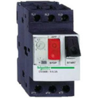
Motor Protection Circuit Breaker (MPCB):
The MPCB shall comply with the latest IEC 60947 –1 (general rules), IEC 60947 – 2 (for
circuit breakers) and IEC 60947-4-1 (motor starters). The MPCB shall be suitable for AC3
duty applications (motor applications) at 415V, 50Hz. The MPCB shall have a typical electrical life of 100000 operations (at AC3 duty). It will be available as three-pole device.
The MPCB shall be of current limiting type with a range of breaking capacity of 10 kA to 100 kA at 415 V, 50Hz.
It should be resistant to flame, shock and vibration to support the use of MPCB in adverse
condition.
condition.
The MPCB should have built in phase loss prevention. The MPCB shall have continuously
adjustable thermal overload setting from 60% – 100% (approx) of frame’s rated current (A)
and the magnetic pick-up (for short circuit protection) should get automatically adjusted to offer coordinated protection. The thermal elements (overload protection) should include automatic compensation for ambient temperature variations.
In order to ensure maximum safety, the power contacts will be isolated by a chamber from
other functions such as operating mechanism, the enclosure, the release, the auxiliaries .The operating mechanism of the motor circuit breaker will be snap action for opening and closing with free tripping of the operating handle. All the poles will trip open and close
simultaneously. Because they are suitable for isolation, these circuit breakers, in open position, provide an adequate isolation distance & indicate the actual position of moving contact by the position of the operator. All live parts are protected against direct finger contact from front.
The state of operation will be clearly indicated through “ON”, “OFF” & “TRIP” position.
The MPCB should be capable of 100% discrimination and Type 2 co-ordination wherever
required, and the manufacturer shall furnish a selection chart for the same. Co-ordination
type 2 in accordance with the tables tested and certified by an official laboratory (LOVAG) or other official laboratory.
required, and the manufacturer shall furnish a selection chart for the same. Co-ordination
type 2 in accordance with the tables tested and certified by an official laboratory (LOVAG) or other official laboratory.
The MPCB shall have built in facility for padlocking in ‘OFF’ position. The MPCB shall have
provision for mounting electrical auxiliaries like ON / OFF indication, TRIP indication, remote switch-off through shunt or under voltage coil and panel building accessories like door interlock, common bus bar, etc. the addition of electrical control or rotary control must neither hide nor lock the adjustments of the breaker.
provision for mounting electrical auxiliaries like ON / OFF indication, TRIP indication, remote switch-off through shunt or under voltage coil and panel building accessories like door interlock, common bus bar, etc. the addition of electrical control or rotary control must neither hide nor lock the adjustments of the breaker.
The auxiliaries will separated from the power contacts and will be common for the complete range. The addition of the auxiliaries will not increase the volume of the device
The motor circuit breaker will have a combination kit for the assembly of a compact motor
starter with the associated contactors.
starter with the associated contactors.


