Introduction:
AC induction motors are the vital elements in any production process and hence constitute majority of loads in Industry and other installations. This note elaborates on MCCB selection for motor application.
MCCBs are used for overload, short circuit, earth fault and neutral protections. However selection parameters change with respect to the loads & applications.
Typical Selection parameters:
MCCBs are used for overload, short circuit, earth fault and neutral protections. However selection parameters change with respect to the loads & applications.
Typical Selection parameters:
- Current rating
- Breaking capacity
- Type of protection- Thermal or Micro processor based
- System voltage
Motor characteristics being unique, needs to be considered while selecting switchgear for motors.
Motor Starting Current:
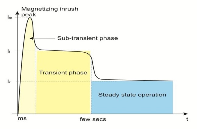
Motor starting current is one of the most important electrical parameter of motor to understand its electrical characteristics. The current drawn by the motor in different phases is shown in the diagram below.
- Sub transient phase
- Transient phase
- Steady state operation.
Transient phase
We are aware of the locked rotor current (LRC) encountered while starting any induction motor. The magnitude of LRC (generally published by Manufacturer) varies from about 6 to 8 times of the rated full load current of the motor (RMS value); variation is mainly due to motor design & construction.
The duration of this current is dependent on starting methods as well as connected loads. The starting times can vary from 30-40 seconds for e.g. centrifugal pump, to tens of seconds depends upon loads & applications. Careful consideration must be given to both the magnitude and the duration of the starting current.
Sub-transient phase
During the initial phase of motor starting, there exists a sub transient current, which is generally known as inrush current or peak current. The duration of this current is generally in milliseconds.
This current is due to magnetising inrush component of the motor starting current. Motor circuits are highly inductive. Motor can be started at any point of time i. e. at any point on voltage wave of the circuit. Depending on the initiation of the circuit i.e. point on the voltage wave, the LRC is offset or shifted by a DC component, this offset is called an asymmetrical current (peak current). Please refer below diagram. The magnitude of the
asymmetry is directly related to X/R ratio of the circuit. By theoretical and empirical means it is established that the maximum ratio between peak and LRC can go upto 2.2
Different Starter methodologies:
Most commonly used motor starting methods are DOL (Direct on Line) or Star- Delta transition. However to limit the very high starting current of the motor, many other starting methods are also developed. Table below summarizes different methodologies and their starting currents. However it is to be noted that every method is used for peculiar application which has to be studied in depth for the proper selection.
Starting method – Starting current /multiples of rated current
DOL: 6 to 8
Star- Delta: 2 to 3
Auto Transformer: 2 to 3
Soft Starter: 3 to 5
VFD: 1.5
However Maximum values can go up to +/- 20%
Starting method – Starting current /multiples of rated current
DOL: 6 to 8
Star- Delta: 2 to 3
Auto Transformer: 2 to 3
Soft Starter: 3 to 5
VFD: 1.5
However Maximum values can go up to +/- 20%
Hence to understand the switchgear selection and especially MCCB selection for motor, the knowledge of motor starting currents, the starting duration and the starting methodology is most important.
Device co-ordination:
The devices which are commonly used in a motor feeder are
1. Short-Circuit Protection Device (SCPD)- typically an MCCB, Fuses or a Switch Fuse unit
2. Switching device, such as a contactor
3. Protection device against overload, such as a thermal or electronic relay
With reference to the behaviour of the above devices against short circuit, IS/IEC 60947-4 standard has defined two types of co-ordination typologies- Type 1 & Type 2 co-ordination.
Type 1 co-ordination:
According to standard, under short-circuit conditions, type “1” coordination allows damage to the contactor and the overload relay; the starter may be inoperative after each operation. As a consequence, contactor, relay, circuit breaker or fuse could not be able to operate/use without repairing or replacement of parts. However, the Standard prescribes that these devices do not cause damages to people or installations.
Type 2 co-ordination:
According to standard, under short-circuit conditions, type “2” coordination allows the risk of contact welding, provided that the contacts themselves can be easily separated (for example through a screwdriver) without significant deformations. This type of coordination requires that the contactor or the starter do not cause damages to people or installation and that they are able to resume operation after restoring of the standard conditions.
“Type 1” co-ordination permits use of devices with lower sizes hence there is an initial cost saving. This leads to quite unsafe situations because devices get damaged on fault. Replacement of devices increases the production downtime as well. “Type 2” coordination meets higher safety requirements and in case of fault, the switching and protection equipment could start operating again without being replaced hence minimise the risk of production downtime.
Type 2 coordination charts are provided by the switchgear manufacturer, it is always recommended to follow the same.
MCCBs
MCCBs for Motors:
While selecting an MCCB for motor application, it is recommended that the instantaneous release setting in the MCCB is set to a value higher than the highest anticipated magnetising inrush current, while switching-on the motor.
The values for Magnetising inrush current (sub transient phase) are higher in case of high efficiency motors as compared to standard efficiency motors. Basically for energy efficient motors, X/R ratio of the system is higher hence the asymmetry component is also higher. By theoretical and empirical means it is established that the maximum ratio between peak and LRC can go upto 2.5 for high efficiency motors.
The values for Magnetising inrush current (sub transient phase) are higher in case of high efficiency motors as compared to standard efficiency motors. Basically for energy efficient motors, X/R ratio of the system is higher hence the asymmetry component is also higher. By theoretical and empirical means it is established that the maximum ratio between peak and LRC can go upto 2.5 for high efficiency motors.
Standard efficiency motors:
Typical Magnitude of LRC (It): 6 times the motor rated current (Ir)
Transient inrush current (peak): 2.2 x 6 Ir = 13.2Ir
Peak value of non trip of MCCB= 1.414*0.8* Imag
Transient inrush current (peak): 2.2 x 6 Ir = 13.2Ir
Peak value of non trip of MCCB= 1.414*0.8* Imag
(Imag (Inst setting of MCCB) = X In, In: Current rating of MCCB)
Hence to avoid nuisance trip, 1.414*0.8* Imag > 13.2Ir
Hence, Imag > 11.67In
Hence, Imag > 11.67In
High efficiency motors:
Transient inrush current (peak): 2.5 x 6Ir= 15Ir
Peak value of non trip of MCCB= 1.414*0.8* Imag
Peak value of non trip of MCCB= 1.414*0.8* Imag
(Imag (Inst setting of MCCB) = X In, In: Current rating of MCCB)
Hence to avoid nuisance trip, 1.414*0.8* Imag > 15Ir
Hence, Imag > 13.26In
Hence MCCB used for motor back up protection should have instantaneous settings (Imag) higher than the transient inrush current (peak) of the motor.
Hence MCCB used for motor back up protection should have instantaneous settings (Imag) higher than the transient inrush current (peak) of the motor.
Contactor & Relay selection with Motor Protection Range MCCBs:
It is observed many times, that whenever a customer wants to replace Switch-Fuse Combination in a motor starter feeder with an MCCB, he simply removes the Switch-Fuse Combinations and replaces the same with an equally rated MCCB. Unfortunately, the user does not pay any attention to the adequacy of the short time withstand capabilities of the contactor & the overload relay, with the revised SCPD (i.e.) MCCB.
It is to be noted that when a particular frame of contactor and relay were suggested for use with a switch-fuse combination unit, they were sized based on the I2t let through energy of the Fuse, which would clear a short circuit. As HRC fuses are fast acting (typically operating within very few milli-seconds for a heavy short circuit fault), the energy let through would also be less during a short circuit and thus the contactor and relay would be subjected to a lesser degree of short circuit stresses. Hence, they would be sized accordingly.
However, when the switch-fuse combination is replaced with an MCCB, now during a short circuit, the MCCB would clear the fault. Even with the most advanced current limiting type of MCCBs, the fault clearing time would be around 10 milli-seconds and thus the energy let through would be higher during a short circuit, than that with a HRC Fuse. Now, the smaller contactor and the relay – which were actually selected for the shorter let-through with HRC fuses – could not handle the increased let- through, with MCCBs and thus would damage. Thus, what was Type-2 Coordination with Switch-Fuse combination gets converted into Type-1 Coordination with MCCB now. Thus, it leads to damage to starter components and increased production downtimes.
To avoid this, it is always recommended to use the respective ‘type 2’ charts provided by the switchgear manufacturers.
Effect of selecting the wrong MCCB:
For motor applications, manufacturers recommend to use MCCBs designed especially for motor protection. Selection of MCCB is recommended as per type “2” co-ordination charts published by respective manufacturers.
In case if MCCB used for motor back up protection also needs to be used for overload protection of motor, care has to be taken to match the overload curve of MCCB with that of motor. This will ensure no damage to the motor in case of overloads. However life of contactor by design is much higher than that of MCCB. Hence above solution will give much lesser life and therefore not preferred. Also if MCCB is used then there is no true protection against the single phasing of motor which can be achieved in case of overload relay. Hence this solution shall not be preferred and it is recommended to abide by the type “2” charts.
In case VFDs or soft starters are used for motor protection, then High speed fuses (generally termed as semi conductor protection fuses) should be used as SCPD and not MCCB because electronic circuit (Thyristor) will get damaged by the time MCCB will clear the short circuit fault (less than 10ms).